Electroplating Board (EPB)
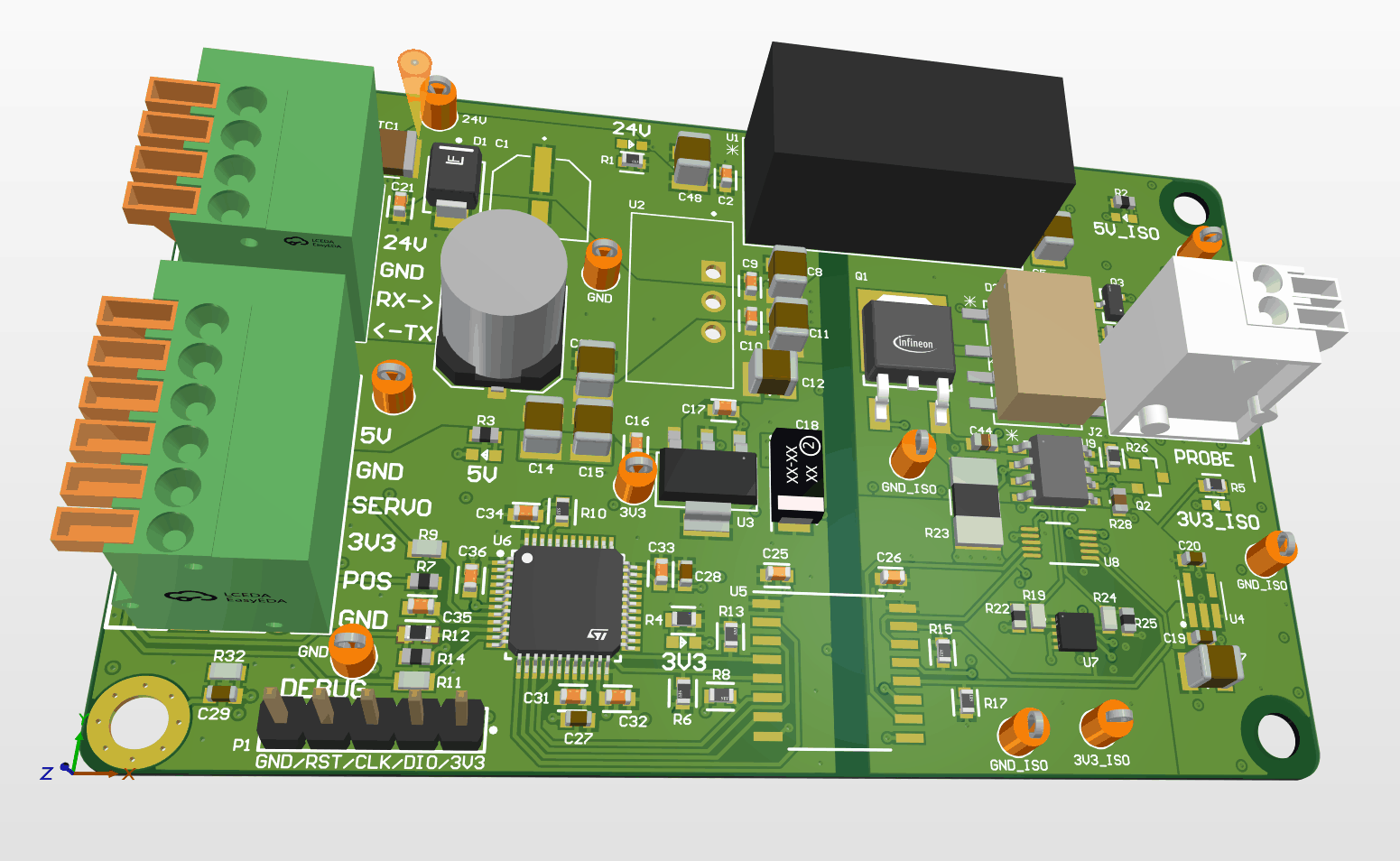
Designed the EPB in Altium Designer and brought it up. It is the current source for my capstone PCB prototyping machine, which electroplates copper onto laser-induced graphene traces, and uses an STM32G431 for software control.
- 16-bit DAC setpoint and ADC readback over isolated SPI, 15nA resolution on the low range
- Cell side galvanically isolated from printer ground, keeping stepper noise off the sense signal
- Communicates with the printer's Klipper host over UART and drives the probe servo
- Bench verified current accuracy of ±0.2% from 1mA to 600mA and ±0.3% from 1µA to 1mA
Design
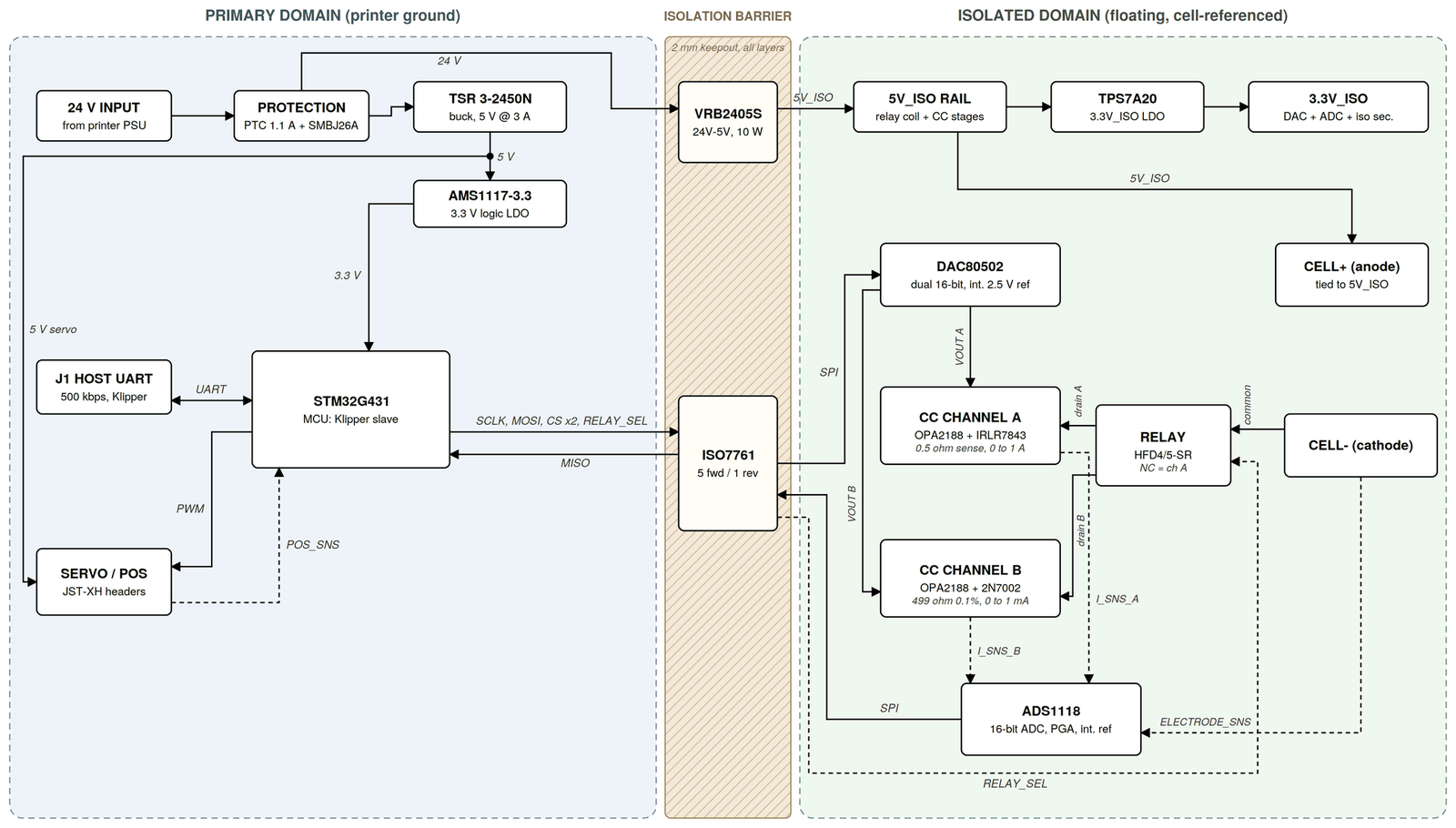
The board has two power domains. The primary side shares the printer's ground. The isolated side floats with the plating cell.
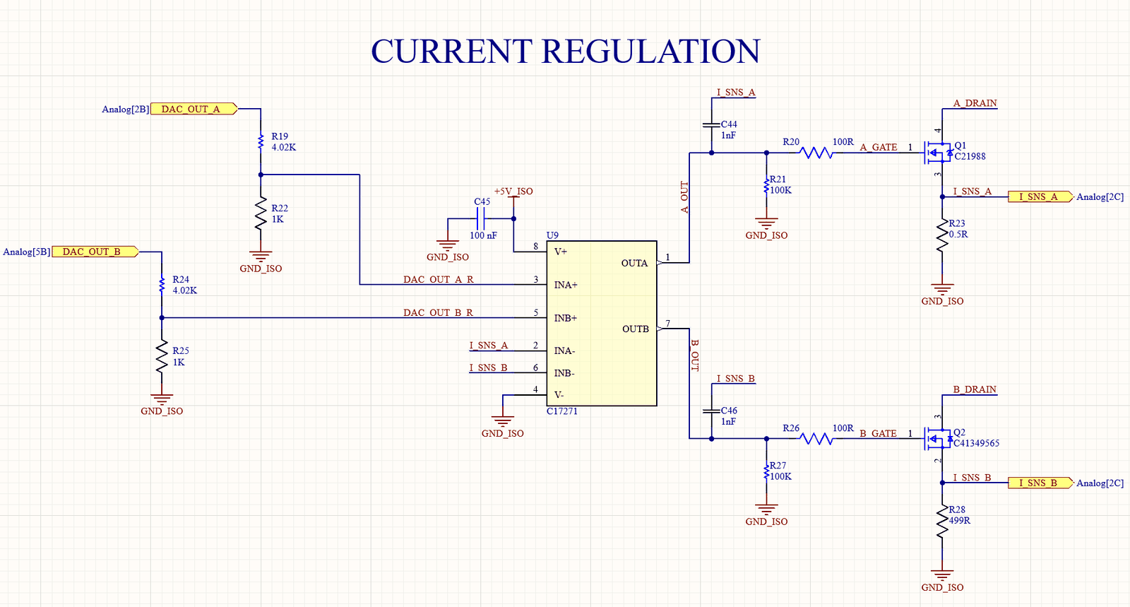
Klipper on the printer sends current commands to the MCU over UART. The MCU passes the setpoint over SPI, through the isolator, to a DAC on the cell side, which drives a feedback circuit that holds the plating current at the setpoint. A relay picks between the two feedback ranges, 0 to 1mA and 1mA to 1A, and an ADC reads the actual current back over the same isolated SPI.
Bringup and Validation
Current regulation was brought up on the bench, sweeping setpoints across both ranges against a bench meter. The board then went into the capstone machine, where the firmware, servo control and ADC readings were brought up.