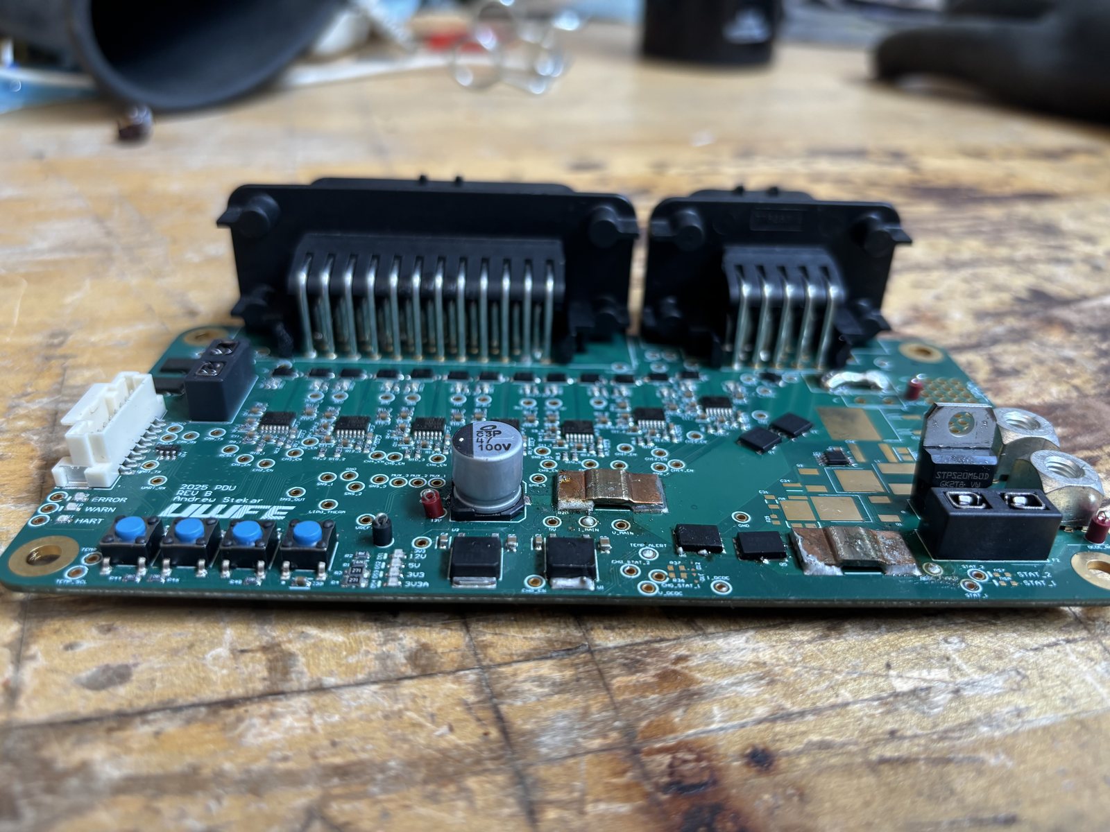
Low Voltage Power Distribution Unit (PDU)
Designed the PDU in Altium Designer and brought it up. It distributes 12V to our FSAE car's low-voltage system and uses an STM32F7 for software control.
- Supplies up to 30A continuously to 14 separate loads (7.5A max per load)
- E-fused load channels with status LEDs that reset themselves before faulting the car (previously blade fuses)
- An ideal diode switches seamlessly between the DCDC and the LiPo, DCDC first
- Charges the LiPo while the DCDC supplies the car, current adjustable in firmware up to 10A
- High side current sense on every load and source channel, read by the MCU for power logging
The Old PDU
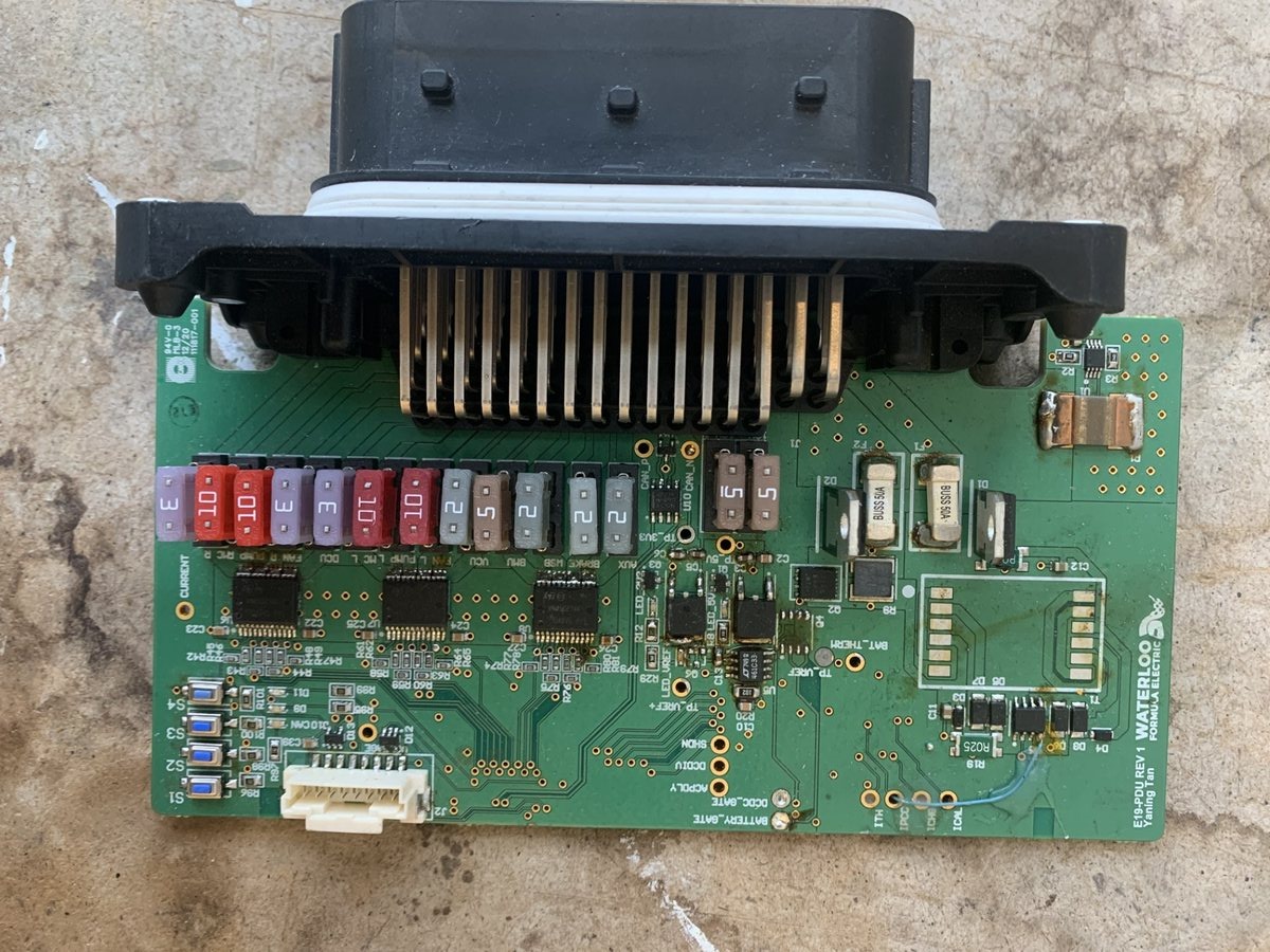
- Blade fuses: when one blew you measured every fuse to find it, then swapped it by hand
- The backup battery charging circuit never worked
- A low side shunt put the board ground above the connector ground, a grounding setup we did not like
The 2025 PDU
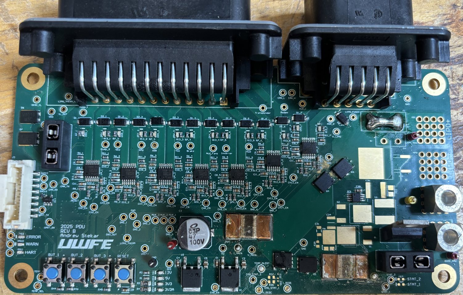
- E-fused load channels report the blown channel and reset themselves, no fuses to replace
- The new LiPo charging circuit works and is validated up to 4A
- Current sense moved to high side shunts, one clean ground
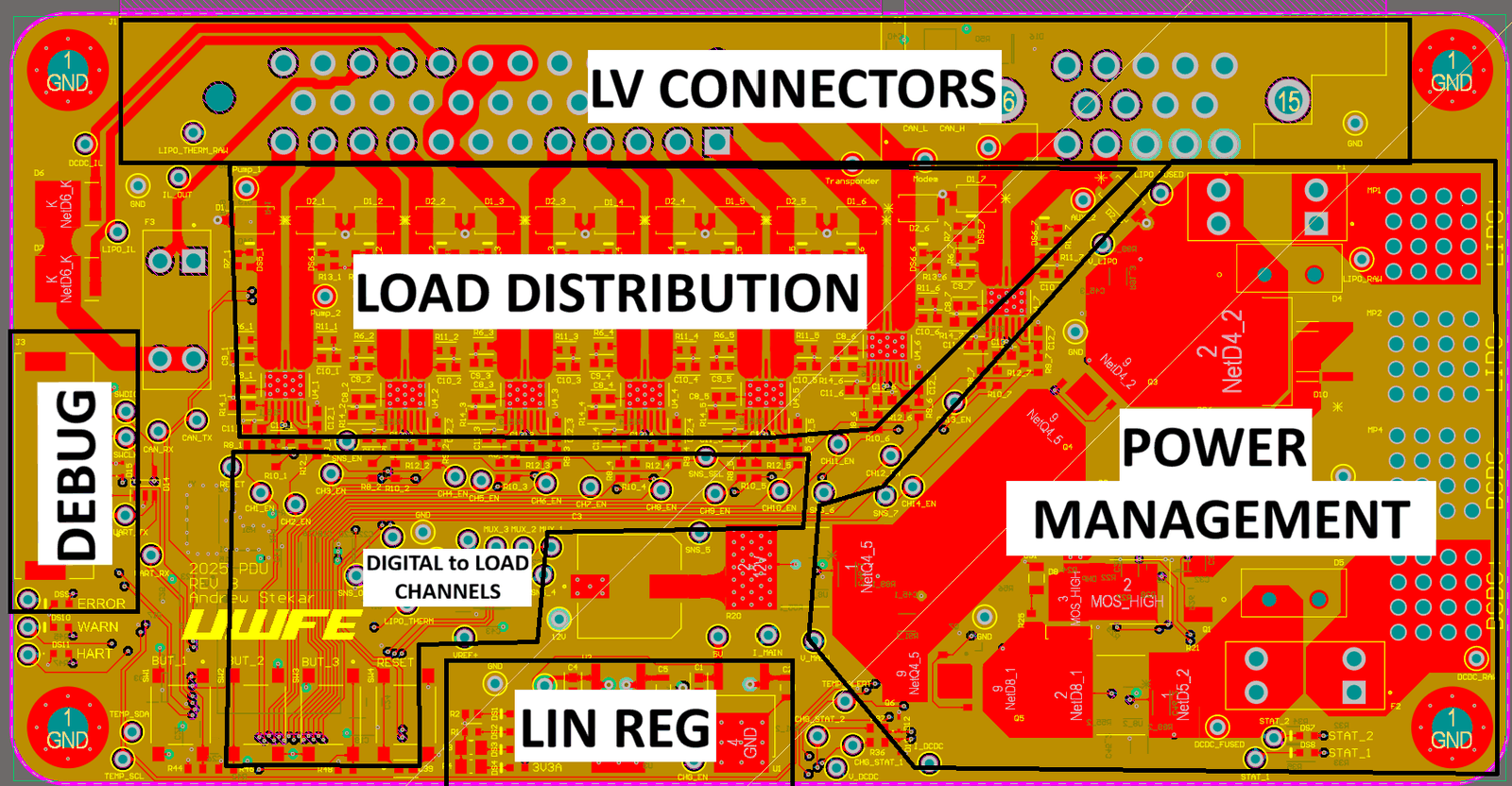
Layout
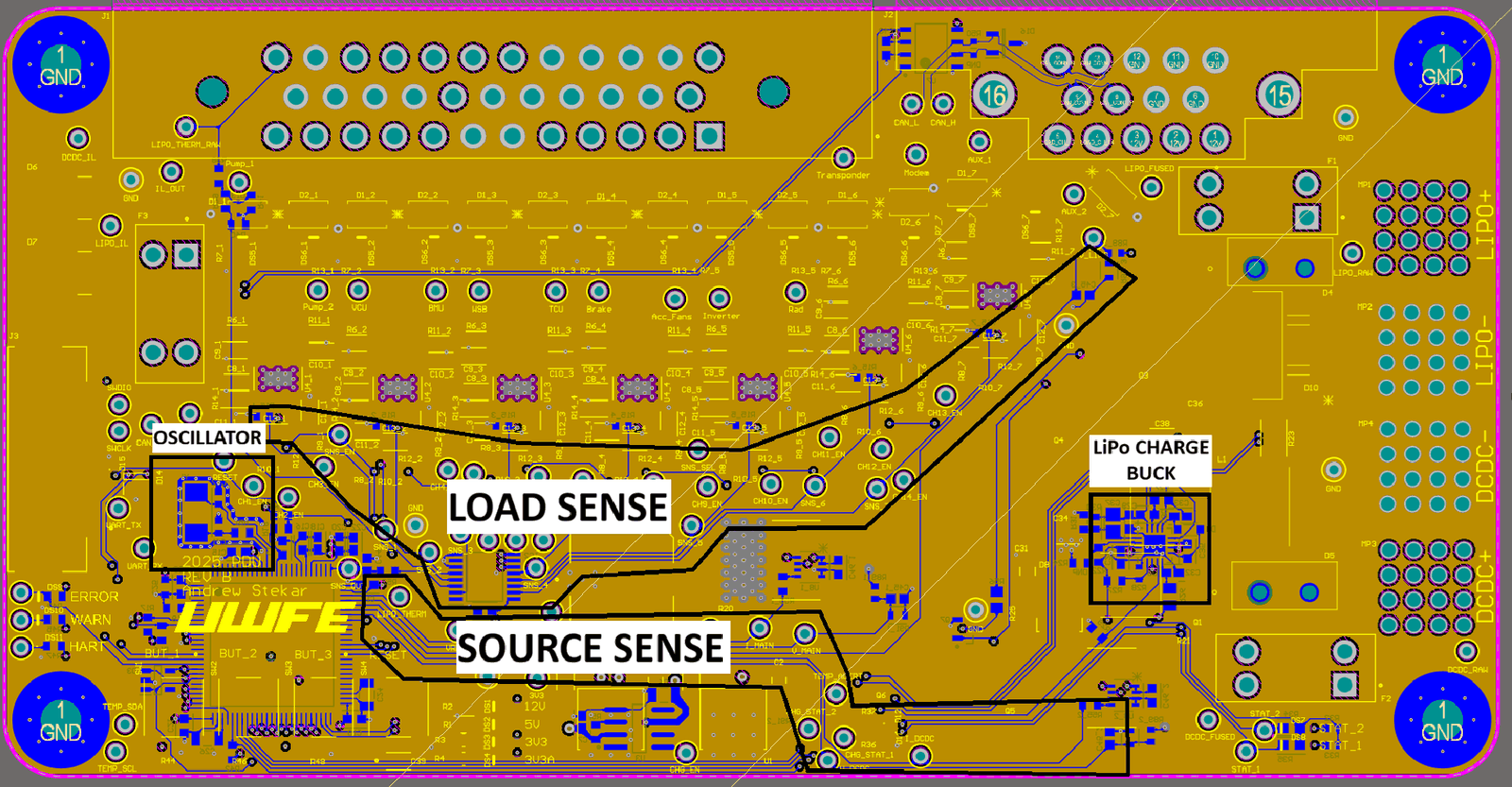
Analog and high speed digital sit on opposite sides of the board, on 6 layers with signal and power layers tightly coupled to ground planes. Trace widths were sized in Saturn PCB, and power enters through 180A press-fit terminals.
Bringup and Validation
Thermals were tested in open air with a 300W e-load. Pulling 7.5A through adjacent channels gave a 30°C rise at the AMPSEAL connectors, and 30A into the board gave a 30°C rise on the power management side. On the car, software immediately identifies which channel faulted.