Project Details
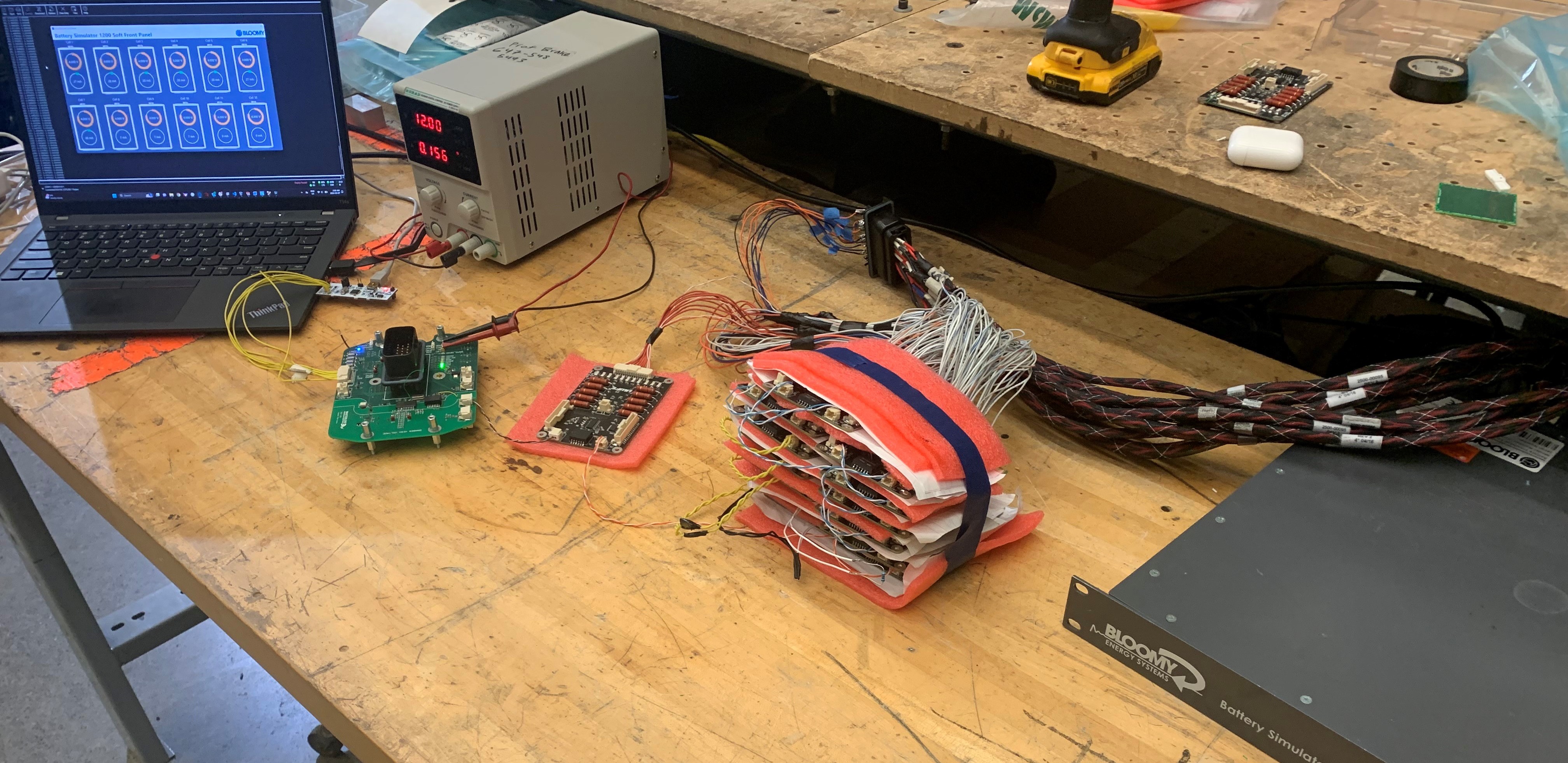
- To manage our new 588-volt battery, we created a custom battery management system (BMS). It is comprised of 14 BMS boards, each responsible for measuring the voltage, temperature and balancing state of 10 series cells in our battery. I was responsible for updating and validating our previous BMS firmware before using it in our car. Below is an image of my test setup.
-
Cell Voltage Simulation
In order to power the BMS, I used a Bloomy Battery Simulator, which can generate 12 isolated voltages to simulate the individual cells. To power all 14 boards (140 total cells), I created a power distribution harness that splits 10 voltage channels into 140. This allowed me to test the following BMS functionalities:
1. Voltage Measurements
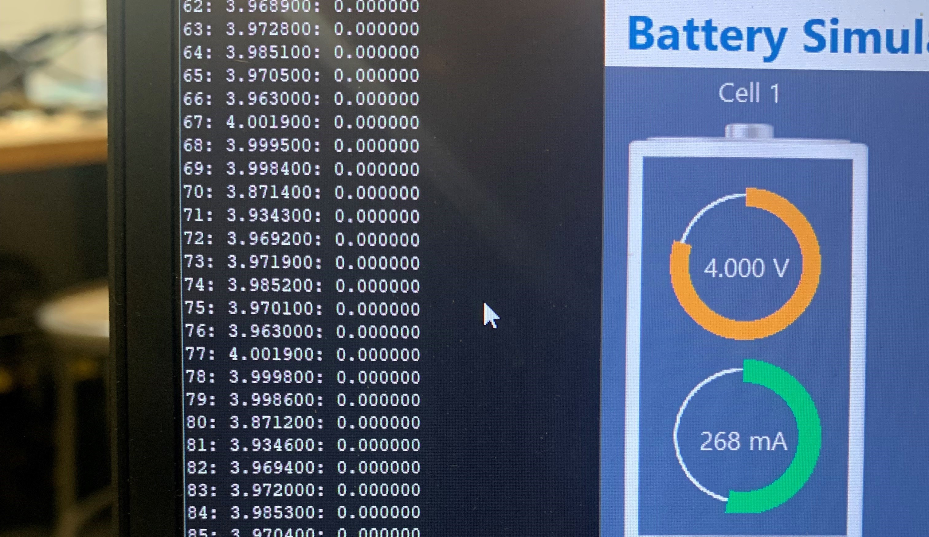
The BMS is controlled by our car's battery management unit. It sends a request to read voltages of all 140 cells and ensures that they are within a safe range. By running the Bloomy at different voltages and viewing the BMU's output over UART, I was able to ensure that these measurements were accurate and handled correctly. Below is an image of the voltage outputs.
-
2. Temperature Measurements
Because of our new battery pack, I needed to remap the thermistor positions in our segments to our firmware. I then checked all 189 thermistors, heating each one and making sure that the BMU was measuring the correct temperature.
-
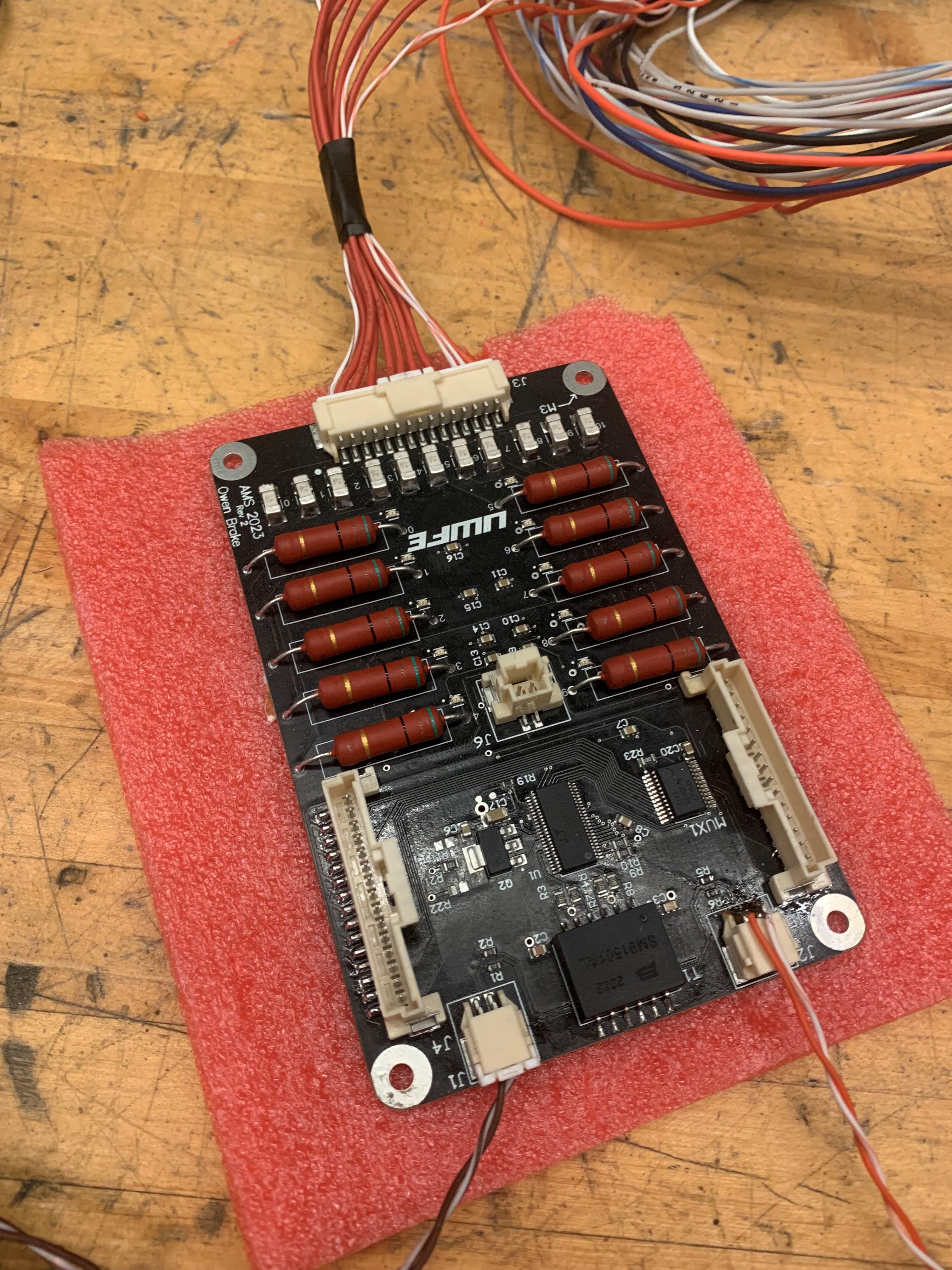
3. Balancing
During charging, we use passive balancing to ensure a balanced battery pack. This is done by discharging any cells that charge too quickly using a resistor. I first remapped our cell configuration in firmware, then validated that we could successfully enable and disable all 140 cells from the BMU.