Project Details
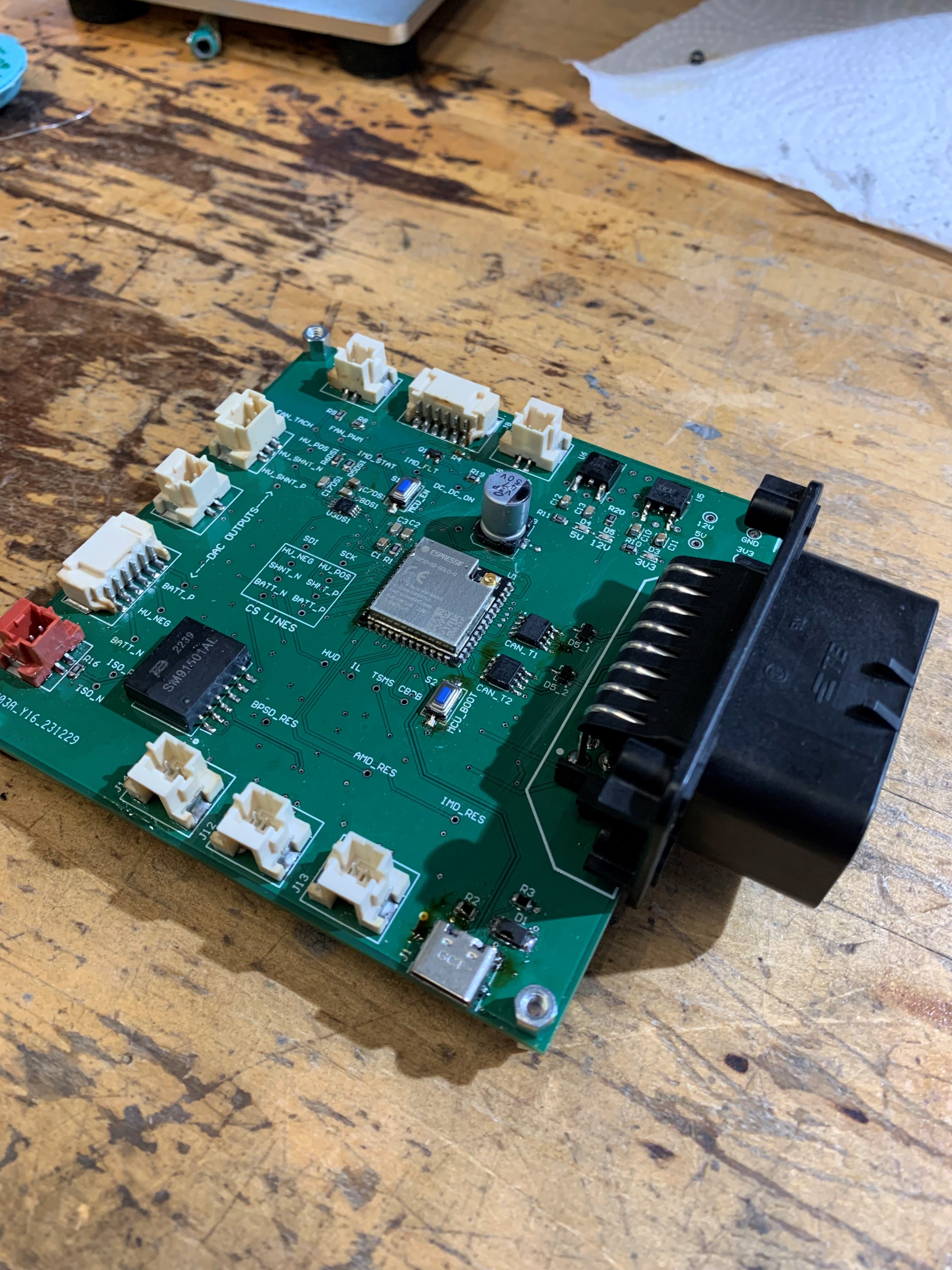
- Led a team of 3 members to design and assemble a 4-layer hardware-in-the-loop PCB to test our car's custom Battery Management Unit (BMU) using Altium Designer. This board is capable of reading and simulating 22 individual signals, ensuring the functionality of 3 main subsytems on the BMU:
1. The shutdown circuit
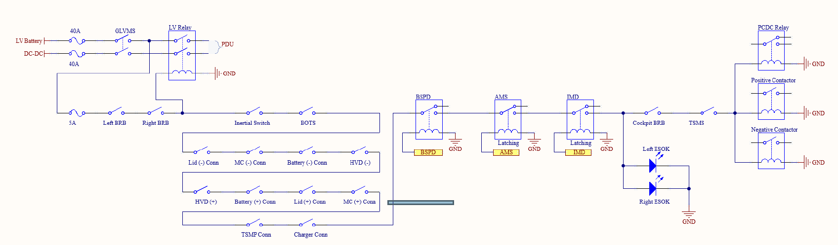
The shutdown circuit is a hardware safety circuit on the car capable of disabling high-voltage when a fault occurs. The circuit is comprised of many different sensors and switches, some of which are managed by the battery management unit. The HIL board is able to simulate their fault conditions, as well as check for a proper response from the BMU through CAN. A diagram of our safety circuit is below:
2. The Battery Management System (BMS)
We have a custom BMS that communicates over isoSPI to 14 separate LTC6804 chips in a daisy-chain configuration. Using the BMU HIL, we can verify that the main isoSPI transceiver located on the BMU is working as expected.
3. High-Voltage Measurements
The BMU takes voltage and current measurements from our HV bus. This information helps us with things like our precharge, and other safety checks while driving. The BMU HIL can simulate all of these inputs using 12-bit DACs.
It also checks some other signals, like fan speed and CAN communication on the BMU.